
Liste des produits
Contactez-nous
Courriel : qiao@hvtest.cc
Portable:+8615871365102
Quelle est l'application : +8615871365102
-
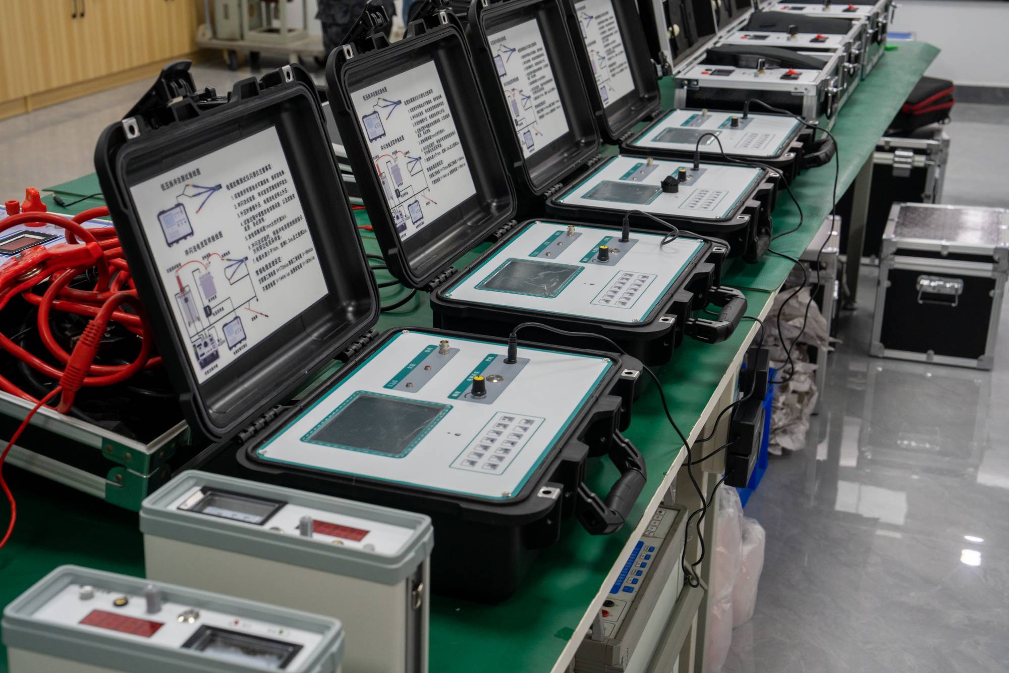
Why is DC resistance measurement so important? This instrument tells you the answer
2026-06-05In the maintenance and testing of electrical equipment, the measurement of DC resistance is a crucial step that cannot be ignored. It's like giving a 'health check' to the device, which can help us detect potential problems in a timely manner. What is a DC resistor? Why is its measurement so crucial? What other useful tools can help us handle it? Today, let's talk about this topic.What is a DC resistor?Simply put, DC resistance is the obstruction encountered by current flowing in a DC circuit. Imagine the water flow in a pipe. If there are wrinkles or blockages in the pipe, the water flow will be obstructed, just like a resistor in an electrical circuit. For electrical equipment, its conductive components (such as transformer windings, switch contacts, etc.) have a certain resistance.What are the factors that affect DC resistance?The material itself: Different conductive materials, such as copper and aluminum, have different electrical resistivity.Length and cross-secti
PLUS -
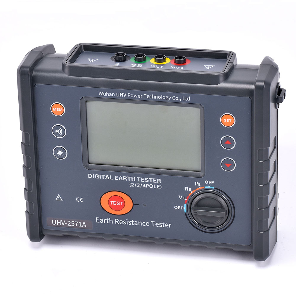
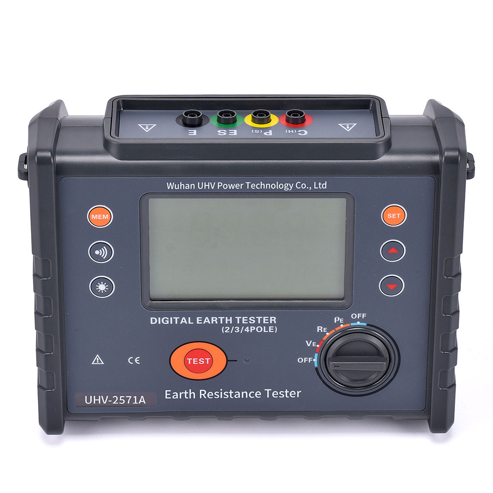
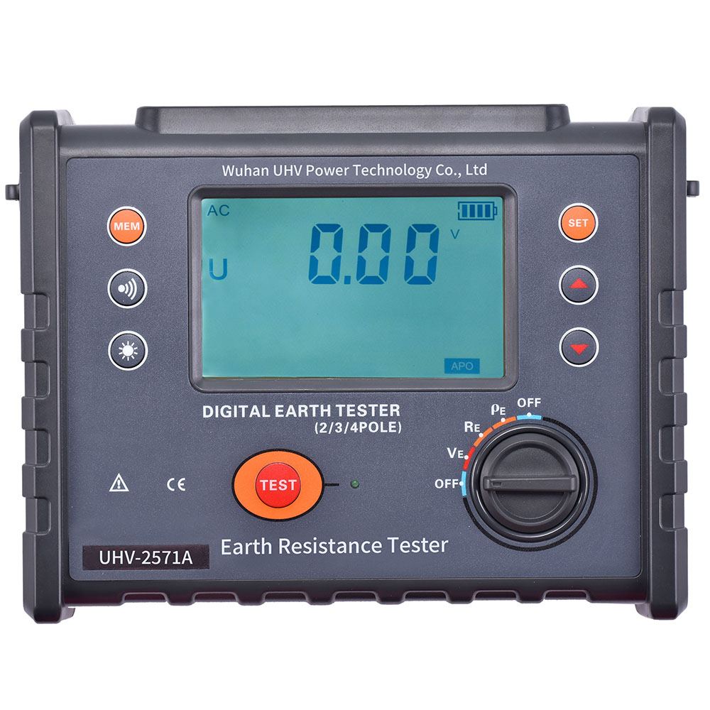
Why does your circuit test get stuck? It's time to learn about the resistance circuit tester!
2026-06-05In the electronic world, stable operation of circuits is crucial. But sometimes, even if we are cautious, we may encounter various obstacles. Among them, accurate measurement of circuit grounding resistance is particularly important. Today, let's talk about how to use a reliable assistant - a resistance circuit tester, to make your circuit testing twice as efficient.What is a resistance circuit tester?Simply put, a resistance circuit tester is an instrument specifically designed to measure the resistance of the grounding circuit in a circuit. It calculates the total resistance of the grounding circuit by injecting a certain current and measuring the voltage drop. This value is directly related to the safety performance of electrical equipment, especially in the event of a fault, whether the fault current can be quickly and effectively introduced into the ground to protect personal and equipment safety.What are the "behind the scenes" factors that affect grounding resistance?To make
PLUS -
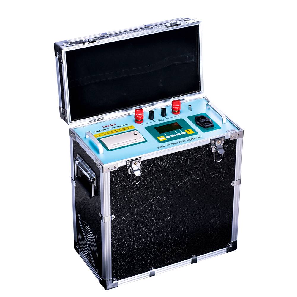
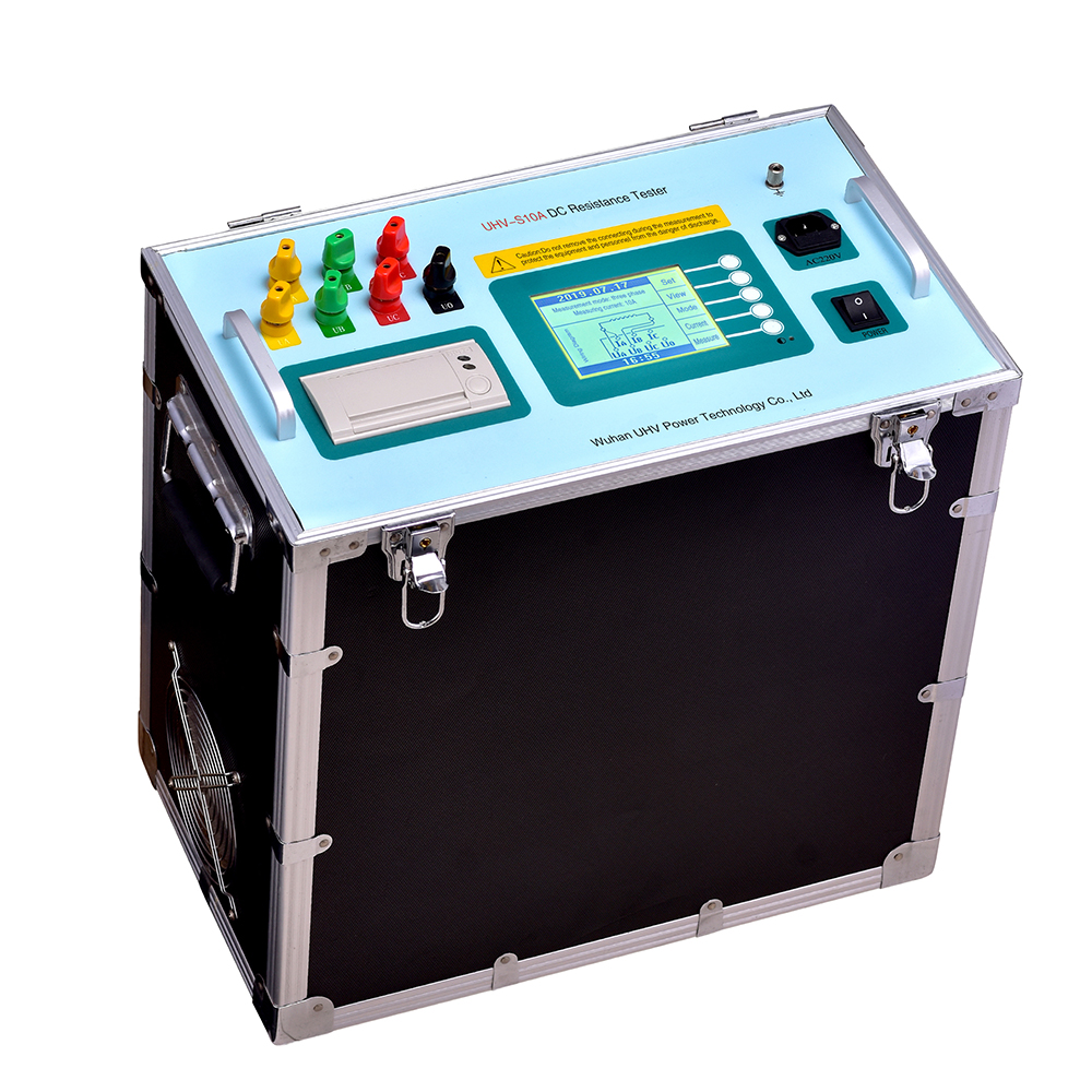
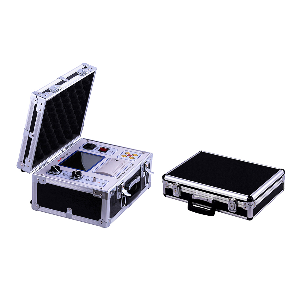
Recommendation: DC resistance rapid measuring instrument, doubling the efficiency of electrical detection!
2026-06-04In the field of electrical equipment maintenance and testing, DC resistance rapid measuring instruments play a crucial role. It is not only a measuring tool, but also the "eyes" that ensure the safe and reliable operation of electrical equipment. What exactly is this device that sounds a bit technical?What is a DC resistance rapid measuring instrument?Simply put, it is an instrument used to quickly and accurately measure the DC resistance of various electrical equipment, such as transformers, switches, motor windings, etc. The DC resistance of electrical equipment is a key indicator for evaluating its insulation performance, connection reliability, and determining the presence of internal faults such as wire breakage and poor contact. Traditional methods may be time-consuming and labor-intensive, while DC resistance rapid measuring instruments can significantly improve efficiency and reduce downtime.Influencing factors and clever responsesThere are many factors that can affect the meas
PLUS -
DC Voltage Generator: Science and Applications Behind Stable Output
2026-06-03In the field of electronics and electrical engineering, there is a widespread demand for stable and controllable DC voltage. And the DC voltage generator is a powerful tool to meet this demand. What exactly is it? What are the key "tricks" worth understanding?What is a DC voltage generator?Simply put, a DC voltage generator is a device that can generate stable and constant directional DC electricity. Unlike the alternating current we use in our daily lives, the direction of current in direct current is single. A stable and reliable DC voltage source is crucial in various precision instruments, electronic equipment testing, and insulation withstand voltage experiments. For example, in the research and production of power equipment, it is necessary to accurately control the output DC voltage to simulate various operating conditions and ensure the reliability of the equipment.Key factors affecting DC voltage outputTo obtain high-quality DC voltage, several factors cannot be ignored:Filter
PLUS -
Do you know how the cable breakpoint tester works?
2026-06-03In the operation and maintenance of power systems, cable faults in cable lines are a thorny issue, and cable breakpoint testers are a key tool to solve this problem. How does it actually work? Today we will talk about this topic.What is a cable breakpoint tester?Simply put, a cable breakpoint tester is a device specifically designed to detect open circuit faults (i.e. breakpoints) in cable circuits. It can accurately locate the location of breakpoints in complex cable networks through specific electromagnetic principles, greatly reducing the time for fault diagnosis and repair, and providing strong support for ensuring the continuity and stability of power supply.Factors affecting the accuracy of cable breakpoint testingTo achieve the best performance of the cable breakpoint tester, some factors need to be particularly noted:The burial depth and environment of cables: The deeper the cable, the greater the signal attenuation and the greater the difficulty of testing. The properties and
PLUS -
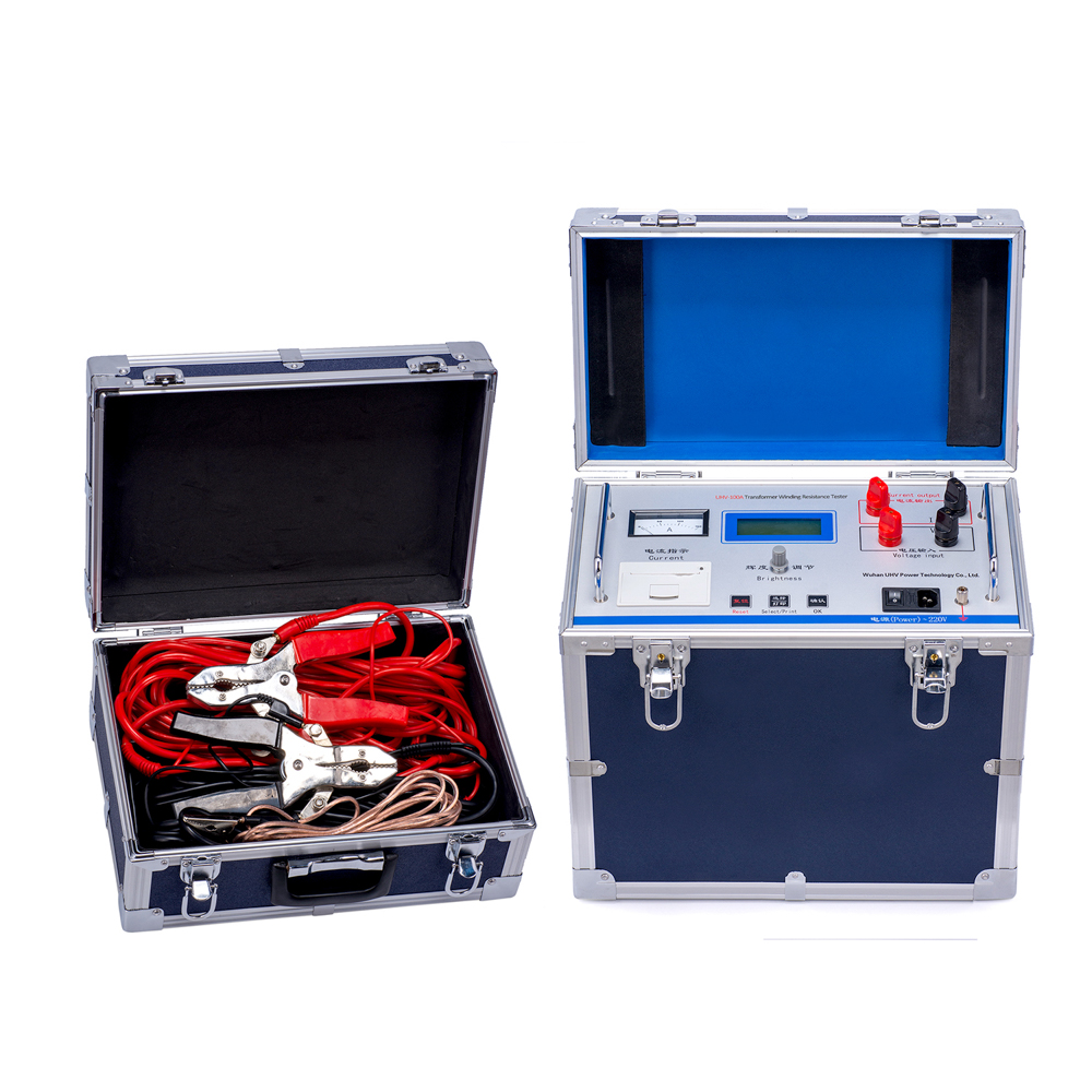
Do you know the secrets of mastering cable DC resistance?
2026-06-03In the stable operation of the power system, cables play a crucial role. As the core indicator for measuring the conductivity of cables, the precise measurement of cable DC resistance is not only related to the efficiency of power transmission, but also the key to ensuring equipment safety. Today, let's talk about this topic and see how Wuhan UHV Power Technology Co., Ltd. has been deeply involved in this field.What is cable DC resistance?Simply put, the DC resistance of a cable refers to the degree to which its conductor obstructs the current when a stable DC current is applied to the cable. The smaller this value, the better the conductivity of the cable and the smaller the energy loss. Imagine, just like the thicker and smoother the water pipe, the easier it is for water to pass through, and the same goes for cables.Factors affecting the DC resistance of cablesTo accurately measure, understanding the influencing factors is the first step. There are mainly the following points:Co
PLUS -

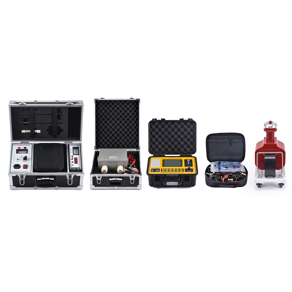
Intelligent Diagnosis: The Secret of Efficient Cable Fault Testing System
2026-06-01In the stable operation of the power system, cables play a crucial role. Once a cable malfunctions, it can affect power supply in some cases and cause safety accidents in others. At this point, an efficient and accurate cable fault testing system becomes particularly crucial. What exactly is this system? How does it work?What is a cable fault testing system?Simply put, a cable fault testing system is a set of equipment and software that integrates multiple advanced technologies, specifically designed to quickly and accurately locate the fault point of power cables. It is like the "doctor" of the power system, able to diagnose the "symptoms" of cables and buy valuable time for repairs. This system typically includes components such as a signal generator, pulse generator, high-voltage power supply, locator, and data analysis software.Factors affecting cable fault testingTo make fault location more accurate, we need to consider several aspects:The type and length of cables: Different mate
PLUS -

Why does your power grid need a 'cable fault comprehensive tester'?
2026-06-01Cables are the 'arteries' that transport energy. Once the cable malfunctions, it can affect power supply at a minor level and potentially cause safety accidents at a severe level. At this point, a comprehensive cable fault tester becomes particularly important. It is like a "health detective" of the power grid, able to quickly and accurately locate "lesions" and restore normal power supply.What is a comprehensive cable fault tester?Simply put, the cable fault comprehensive tester is a device that integrates multiple testing functions, specifically designed to detect and locate the fault points of power cables. It can complete precise positioning of various types of cable faults (such as low resistance, high resistance, flashover, grounding, etc.) from insulation resistance testing and DC withstand voltage testing of cables.What are the factors that affect cable faults?Environmental factors such as humidity, high temperature, and corrosive gases may accelerate cable aging.Aging
PLUS -
Still struggling with cable faults? These tips help you quickly locate yourself!
2026-06-01Cable failure is like a sudden but unavoidable "big test" in the power system. When there is a problem with the power transmission line, resulting in cable failure, the entire power supply system may be paralyzed, which can affect daily life or cause huge economic losses. How can we quickly and accurately locate these "hidden" fault points underground or in equipment? Today, let's talk about the cable fault locator as a reliable assistant and how to better utilize it.What is a cable fault locator?Simply put, a cable fault locator is an instrument specifically designed to detect and locate power cable fault points. It uses various physical principles, such as electromagnetic induction, pulse reflection, etc., to "auscultate" the health status of the cable and ultimately provide the specific location of the fault. Imagine this is like performing a 'B-ultrasound' on a long cable, which can accurately pinpoint the location of the 'lesion'.Factors affecting cable fault l
PLUS -
Exploring cable 'lesions': a magical tool for efficiently locating faults
2026-06-01In the process of power transmission, cables play a crucial role as the "arteries" of the city, transporting a continuous stream of energy. Even the strongest "artery" is inevitably prone to "lesions" - cable failures. Once a malfunction occurs, it will not only affect the stability of power supply, but also bring huge economic losses and safety hazards. At this point, an efficient and accurate cable fault locator becomes particularly crucial.What exactly is a cable fault locator? Simply put, it is an instrument specifically designed to locate cable fault points. Think about it, a cable that is several kilometers or even tens of kilometers long, once there is a problem, searching for that "lesion" in the vast "sea of lines" is like looking for a needle in a haystack without suitable tools! The cable fault locator is the "microscope" or "probe" that allows you to quickly and accurately locate the fault location.What is the 'secret weapon' of cable fault addressable devices?The r
PLUS -
How to locate cable faults more quickly and accurately? You must know these points!
2026-05-29In the power system, cables are like "blood vessels" that transport energy, and the occurrence of cable failures can lead to widespread power outages, affecting normal production and life. How can we quickly and accurately locate the fault point when a cable malfunctions? Today, let's talk about cable fault instruments and see how they become "detectives" in power maintenance.What is a cable fault instrument?Simply put, cable fault instruments are specialized equipment used to detect and locate power cable faults. These instruments use various physical principles, such as electromagnetic induction, pulse reflection, etc., to analyze the electrical characteristics of cables and pinpoint the location of faults. Imagine finding that 'lesion' among countless cables, which is not an easy task, fortunately with the assistance of these high-tech tools.Factors affecting cable fault locationThere are various types of cable faults, which directly affect the difficulty of our localiza
PLUS -

Still troubled by cable faults? These tips help you quickly locate!
2026-05-29In the power system, the stable operation of cables is crucial. Once a fault occurs, it can affect power supply or cause serious accidents. How can we efficiently and accurately identify the root cause of these tricky cable faults? Today, let's talk about cable fault detection instruments and see how they can detect problems with sharp eyes.What is a cable fault detection instrument?Simply put, cable fault detection equipment is a specialized device designed to detect internal or external faults in cables. They can quickly locate the location and nature of the fault point through various physical or electrical principles, greatly shortening the repair time and reducing the scope of power outages.Factors affecting cable faultsEnvironmental factors such as humidity, high temperature, and corrosion can accelerate cable aging.External force damage: Construction excavation, sharp object impact, etc. can all cause physical damage to cables.Equipment aging: The insulation layer of the cab
PLUS -
Fuzzy judgment: How can the intelligent cable fault tester achieve precise positioning?
2026-05-28In the power system, cables serve as the "arteries" for energy transmission, and their stable operation is crucial. During long-term operation, cables inevitably encounter various "difficult and complicated problems" - which are commonly referred to as faults. Once a malfunction occurs, it will not only affect the continuity of power supply, but may even pose a serious safety hazard. How can we quickly and accurately locate the fault point and minimize losses? This relies on the powerful capabilities of the intelligent cable fault tester.What is an intelligent cable fault tester?Simply put, the cable fault intelligent tester is a device that integrates multiple advanced testing technologies and intelligent analysis functions, specifically designed to detect and locate the fault points of power cables. It has made rough judgments like searching for a needle in a haystack in the past, and can accurately analyze the type and specific location of faults through various testing methods such
PLUS -
Zinc oxide lightning arrester comprehensive tester: precise protection of the "firewall" of the power system
2026-05-27In the safe operation of the power system, zinc oxide arresters play a crucial role, acting as a finely tuned "firewall" that effectively prevents damage to equipment caused by lightning strikes and overvoltage operations. To ensure that this "firewall" is always in the best working condition, the zinc oxide lightning arrester comprehensive tester is particularly crucial. What exactly is this seemingly sophisticated device? How does it work?The comprehensive tester for zinc oxide lightning arresters, as the name suggests, is a specialized instrument used to test the performance of zinc oxide lightning arresters. It can measure various key parameters of lightning arresters at once, such as DC discharge voltage, leakage current, resistive leakage current, AC parameters, and insulation resistance. The accuracy of these parameters directly affects the overvoltage protection capability and service life of the lightning arrester.Why is its testing so important?The performance of lightning ar
PLUS -
Is your cable line still 'invisible'? Underground fault tester helps you find the root cause!
2026-05-27The stable operation of underground cables is crucial in the power system. Once a malfunction occurs, locating and repairing it is a daunting task. Today, let's talk about the "Cable Underground Fault Tester", which is a powerful assistant that can make "invisible" faults nowhere to hide.What is a cable underground fault tester?Simply put, a cable underground fault tester is a specialized instrument used to detect and locate fault points (such as short circuits, grounding, wire breaks, etc.) in buried power cables. It can accurately locate the specific location of the fault through various technological means, greatly reducing the time for fault handling and minimizing power outage losses.Factors affecting underground cable fault testingCable burial depth and environment: The deeper the burial, the more severe the signal attenuation and the greater the difficulty of testing. The conductivity of soil, groundwater level, and surrounding metal pipelines can all affect the accuracy of
PLUS -
Six factors affect the reading of electronic grounding resistance tester, Wuhan UHV teaches you how to accurately measure!
2026-05-26In the field of power safety, the reliability of grounding systems is crucial, and electronic grounding resistance testers are key equipment to ensure this reliability. What exactly is it? Simply put, it is an instrument used to measure the resistance value of grounding devices, evaluating the effectiveness of grounding systems by measuring the contact resistance between the grounding body and the earth. The smaller the grounding resistance, the more advantageous it is to guide the fault current into the ground, protecting equipment and personal safety.The 'behind the scenes driver' affecting the reading of electronic grounding resistance testerThere are many factors that can affect the reading of electronic grounding resistance testers, just like a wonderful performance, with various "behind the scenes drivers" at work:Soil resistivity: This is the most crucial factor. The moisture, composition (such as salt content and organic matter content), and temperature of soil can sign
PLUS -
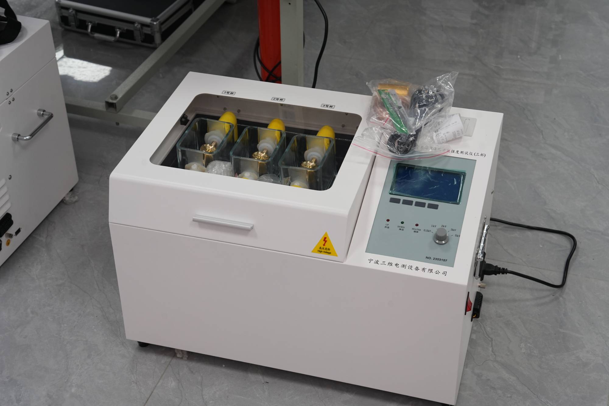
How to choose a reliable oil withstand voltage tester? Let you avoid detours!
2026-05-26Are you troubled by choosing a suitable oil pressure tester? Don't worry, today we will talk about this topic to help you easily grasp the key points of purchasing and avoid pitfalls!What is an oil withstand voltage tester?Simply put, an oil withstand voltage tester is an instrument used to test the insulation performance of insulating oil (i.e. transformer oil, switch oil, etc.). It measures the maximum voltage that the insulating oil can withstand before breakdown, which is the breakdown voltage, by applying a gradually increasing voltage. This indicator is directly related to the safe operation of power equipment, so a precise and reliable tester is crucial.What are the factors that affect the withstand voltage resistance performance of oil?There are many factors that affect the voltage resistance performance of insulating oil, mainly including:Moisture content: Water is the "enemy" of insulating oil, and an increase in moisture will significantly reduce the insulation strength
PLUS -
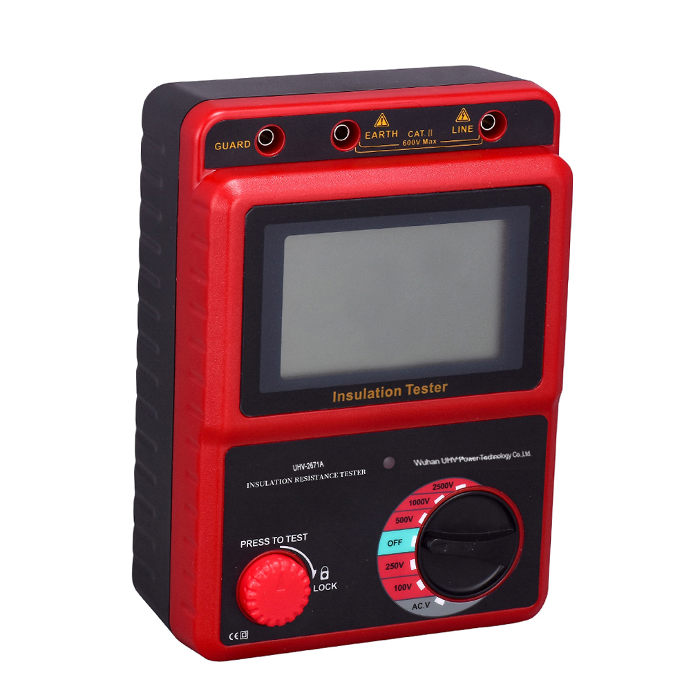
Why does the insulation resistance value of your device fluctuate abnormally? Electronic insulation resistance meter helps you find the cause!
2026-05-26In the operation and maintenance of power equipment, the detection of insulation resistance is a key link to ensure the safe operation of the equipment. Have you ever encountered a situation where the insulation resistance values measured at different times on the same device seem somewhat arbitrary? Don't worry, there may be some "little secrets" hidden behind this that you need to know. Today, let's talk about electronic insulation resistance meters and see how they help us understand these changes.Understand your "assistant": What is an electronic insulation resistance meter?Simply put, an electronic insulation resistance meter is a precision instrument that uses electrical principles to measure the weak current flowing through an insulator (usually the insulation layer of cables, transformers, and other equipment) by applying a certain DC voltage, in order to calculate the insulation resistance value. It is different from traditional shaking meters, more intelligent and dat
PLUS -
90% of equipment failures may be related to it? Unveil the mysterious veil of intelligent insulation resistance tester!
2026-05-25In the world of electrical equipment, insulation is the cornerstone for ensuring safe operation. Once there is a problem with insulation, it can lead to a decrease in equipment performance or serious accidents such as fires and explosions. Is there an efficient and intelligent tool that can provide early warning and prevent potential problems? The answer is - an intelligent insulation resistance tester.What exactly is it?Simply put, an intelligent insulation resistance tester is a professional instrument used to measure the insulation resistance of electrical equipment. It can measure the small current flowing through an insulator by applying a high DC voltage, thereby calculating the value of insulation resistance. This value is a key indicator for measuring the quality of insulation materials and the overall condition of insulation. The term 'poor insulation' often refers to a low insulation resistance value.What are the "behind the scenes" factors that affect insulation resi
PLUS -
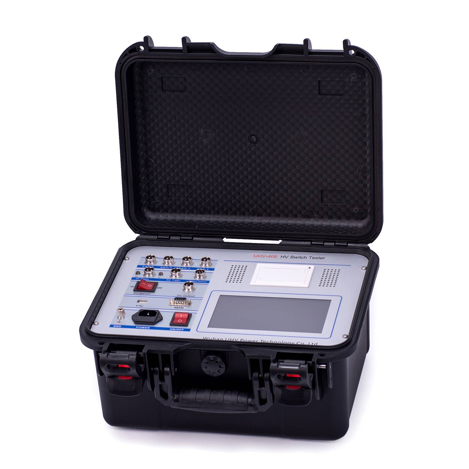
The "temper" of the circuit breaker is good or bad, and the mechanical characteristic test is the final say!
2026-05-25In the power system, circuit breakers are like the "safety guards" of the circuit, quickly cutting off the current when a fault occurs to protect equipment safety. But you know what? The stability of a circuit breaker largely depends on its mechanical characteristics. Today, let's talk about how to conduct mechanical characteristic tests on circuit breakers to keep this' safety guard 'in the best condition at all times.What are the mechanical characteristics of circuit breakers?Simply put, the mechanical characteristics of a circuit breaker refer to the laws and performance of a series of mechanical components during its closing and opening processes. This includes closing/opening speed, contact time of contacts, energy storage of springs, reclosing performance, and so on. These parameters directly affect whether the circuit breaker can operate accurately and quickly at critical moments, avoiding the escalation of accidents.What are the factors that affect the mechanical ch
PLUS


