Years of operational experience both domestically and internationally have shown that DC withstand voltage testing is not suitable for the handover or preventive testing of rubber plastic power wires. Instead, AC withstand voltage testing (frequency range 30-300hz) should be used to ensure safe movement. Cable. This is a groundbreaking change in the development history of preventive testing for power equipment. However, the DC withstand voltage test is still effective for oil immersed paper insulated power wires and should continue to be used. Due to the large capacity of the wires, it is not suitable to use high-capacity power frequency test transformers on site. The advantages of frequency modulation series resonance high-voltage testing equipment are light weight and small power capacity (only 1/30~1/80 of the power capacity of the testing transformer)
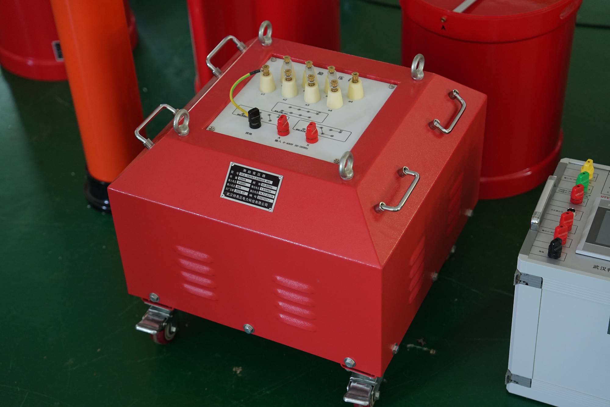
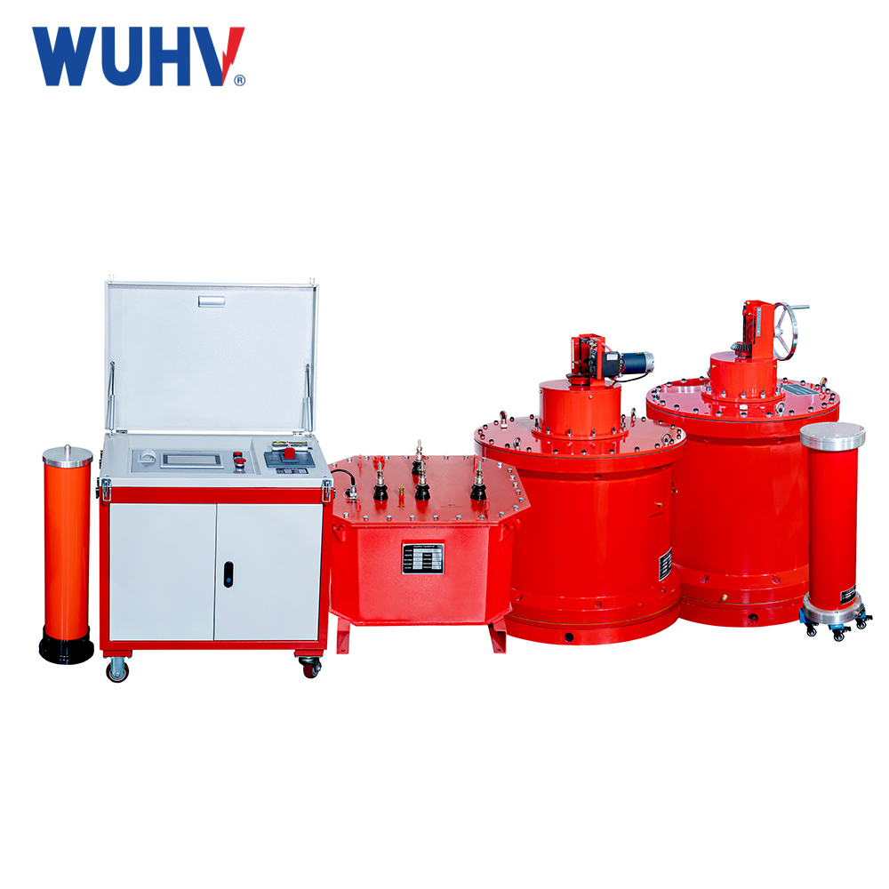
This testing equipment is specifically designed and manufactured for on-site AC withstand voltage testing of rubber and plastic power wires, suitable for handover testing and preventive testing. The main components of the entire equipment include: frequency conversion control box, resonant reactor, excitation transformer, capacitor voltage divider, etc.

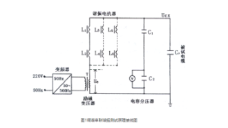
The working principle and wiring of the frequency modulation series resonance high-voltage testing equipment are shown in Figure 1. The 380V/50Hz AC power supply outputs a frequency adjustable voltage of 30-300Hz through a frequency converter, which is sent to the excitation transformer for boosting to 0. -2000v, And a high-voltage main harmonic circuit is formed through the resonant reactor L (resonant reactors can be used in series or parallel, depending on the tested cable, voltage level, and length) and the tested wire CX.
The capacitor voltage divider is a pure capacitive type used for measuring and testing voltage. Firstly, the frequency converter sends a lower voltage ue to the main resonant circuit through the excitation transformer T and adjusts the output frequency of the frequency converter. When the frequency reaches the resonance frequency, the output of the frequency converter will be adjusted

The voltage UCX on the tested object CX reaches its maximum value. At this point, the inductive reactance ZL=WL of the resonant reactor is equal to the capacitive reactance of the tested Zc=1/wCx object, forming a state of mutual compensation (offset). In the main resonant circuit, there is only an equivalent resistance component (such as the effective resistance of the winding and the equivalent magnetic core loss), which can generate a large current at a small UE voltage, thereby harmonizing the tested cable CX. Generated at both ends of the reactor group. After finding the resonant frequency, keep the frequency constant and slowly increase the UE voltage so that the expected test voltage value UX can be obtained on the tested wire Cx.
The relationship between the voltage and current on the measured object during resonance is

The ratio of output voltage UCX to excitation voltage UE is the comprehensive quality factor Q of the test circuit

From the above working principle, it can be seen that:
1. The higher the quality factor, the smaller the required power capacity.
2. The resonant reactor L and the tested cable CX are in a resonant state, forming a good filtering circuit. Therefore, the output voltage UCX has a good sine wave shape.
3. When the tested cable breaks, the resonance condition is lost, but the current of the high-voltage circuit and low-voltage power supply circuit is reduced. Therefore, the arc during insulation breakdown will not expand the fault point, making maintenance easier.


